Stereo calibration using C++ and OpenCV
September 9, 2016
Introduction
Before viewing this, it is recommended that you know how to calibrate a single camera and what is meant by calibrating a camera. You can find a tutorial for the same here:
If you’re just looking for the code, the full implementation can be found here:
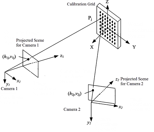
Stereo Setup
The following two images describe a stereo camera setup.
 |
 |
We will use the checkerboard method for calibration. It is required that the intrinsics of each camera be known beforehand. Recall the camera matrix $\mathbf{K}$ as
where $f_x$ and $f_y$ are the focal length of the camera in the x-axis and the y-axis respectively. $(c_x, c_y)$ is coordinate of the principal point. Therefore $\mathbf{K_1}$ and $\mathbf{K_2}$ should be known for both cameras before moving on with stereo calibration.
Stereo calibration will essentially find out the rotation $\mathbf{R}$ and translation $\mathbf{t}$ between both the cameras and this will help us find point correspondences in the left and right image planes.
Let $\mathbf{x}$ and $\mathbf{x’}$ be a point in the left image and right image respectively, then the correspondence relation is defined by the fundamental matrix $\mathbf{F}$ as
You can find a tutorial to calculate $\mathbf{F}$ given $\mathbf{K_1}$, $\mathbf{K_2}$, $\mathbf{R}$, and $\mathbf{t}$ here:
http://souri.sh/2016/fundamental-matrix-from-camera-matrices/
It is advised that in case you do not understand the theory behind stereo vision, then a little bit of reading is to be done before you proceed with this just to get a feel of what is happening and what all these symbols/variables mean. The math behind stereo vision is mostly projective geometry and matrix algebra.
Dependencies and Datasets
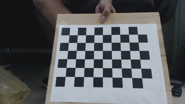
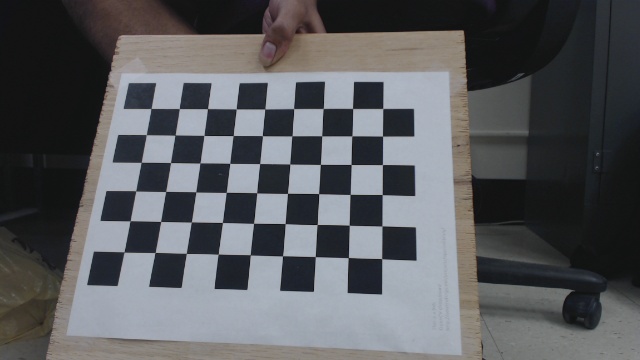
You must have OpenCV 2.4.8+ and libpopt (command line args) to run the code. Also, you should have a dataset of calibration left/right image pairs beforehand of a fixed image resolution. Here are is a sample left/right image pair.
| Left Image | Right Image |
|---|---|
 |
 |
I have made two of my own image sets available here:
https://github.com/sourishg/stereo-calibration/tree/master/calib_imgs
It is recommended to get at least 30 image pairs of the checkerboard in all possible orientations of the checkerboard to get good calibration results.
Note: In this example, a standard 9x6 calibration board is used. The size of the square is 24.23 mm.
Stereo Calibration
The code is almost similar to the one explained here. I will only explain the important parts of the code, and you can find the full source here:
https://github.com/sourishg/stereo-calibration/blob/master/calib_stereo.cpp
vector< vector< Point3f > > object_points;
vector< vector< Point2f > > imagePoints1, imagePoints2;
vector< Point2f > corners1, corners2;
vector< vector< Point2f > > left_img_points, right_img_points;
Declare all the necessary vectors to store the image points and the object points. Image points are the checkerboard corner coordinates in the image whereas object points are the actual 3D coordinate of those checkerboard points.
void load_image_points(int board_width, int board_height, int num_imgs, float square_size,
                      char* leftimg_dir, char* rightimg_dir, char* leftimg_filename, char* rightimg_filename) {

  Size board_size = Size(board_width, board_height);
  int board_n = board_width * board_height;
We create a function called load_image_points to find all the corner points of each image and their corresponding 3D world points and prepare the object_points, left_img_points, and right_img_points vectors. board_n is the total number of corner points in the checkerboard. In our example it is $9\times 6=54$. Note that we also take a bunch of args, but I hope the variable names are self explanatory. Also note that the object points would be same for both the left and right images.
  for (int i = 1; i <= num_imgs; i++) {
    char left_img[100], right_img[100];
    sprintf(left_img, "%s%s%d.jpg", leftimg_dir, leftimg_filename, i);
    sprintf(right_img, "%s%s%d.jpg", rightimg_dir, rightimg_filename, i);
    img1 = imread(left_img, CV_LOAD_IMAGE_COLOR);
    img2 = imread(right_img, CV_LOAD_IMAGE_COLOR);
    cvtColor(img1, gray1, CV_BGR2GRAY);
    cvtColor(img2, gray2, CV_BGR2GRAY);
We loop through all the images in our directory and convert them to grayscale images using the function cv::cvtColor. leftimg_dir is the directory containing the left images and leftimg_filename is the prefix for each image file name. Similar concept for the right images.
    bool found1 = false, found2 = false;

    found1 = cv::findChessboardCorners(img1, board_size, corners1,
    CV_CALIB_CB_ADAPTIVE_THRESH | CV_CALIB_CB_FILTER_QUADS);
    found2 = cv::findChessboardCorners(img2, board_size, corners2,
    CV_CALIB_CB_ADAPTIVE_THRESH | CV_CALIB_CB_FILTER_QUADS);

    if (found1)
    {
      cv::cornerSubPix(gray1, corners1, cv::Size(5, 5), cv::Size(-1, -1),
    cv::TermCriteria(CV_TERMCRIT_EPS | CV_TERMCRIT_ITER, 30, 0.1));
      cv::drawChessboardCorners(gray1, board_size, corners1, found1);
    }
    if (found2)
    {
      cv::cornerSubPix(gray2, corners2, cv::Size(5, 5), cv::Size(-1, -1),
    cv::TermCriteria(CV_TERMCRIT_EPS | CV_TERMCRIT_ITER, 30, 0.1));
      cv::drawChessboardCorners(gray2, board_size, corners2, found2);
    }
Next we use the findChessboardCorners function to find all the checkerboard corners. I would suggest you go through the OpenCV documentation for more details about the arguments of this function. If the corners are found then found is set to true and the corners are further refined by the cornerSubPix function. The drawChessboardCorners function is optional, it only helps you visualize the checkerboard corners found.
    vector< Point3f > obj;
    for (int i = 0; i < board_height; i++)
      for (int j = 0; j < board_width; j++)
        obj.push_back(Point3f((float)j * square_size, (float)i * square_size, 0));

    if (found1 && found2) {
      cout << i << ". Found corners!" << endl;
      imagePoints1.push_back(corners1);
      imagePoints2.push_back(corners2);
      object_points.push_back(obj);
    }
  }
}
Next we store the object points. Ideally we should keep the origin at the camera centre and measure the 3D points of the checkerboard corners manually but you can image how difficult it would be. So we introduce a small but beautiful hack - we keep the world origin as the top left corner point. Mathematically this doesn’t change anything (think how). Now the geometry of the checkerboard helps us find the other 3D coordinates of the corners very easily. The $Z$ coordinate is always $0$ since all the points lie on a plane. Since the square size for this example is 24.23 mm (units are important!) then the other points become $(24.23, 0, 0)$, $(48.46, 0, 0)$ and so on.
Note that if corners are found for both the left and right images then only the points are stored, otherwise that image pair is ignored.
int main(int argc, char const *argv[])
{
  char* leftcalib_file;
  char* rightcalib_file;
  char* leftimg_dir;
  char* rightimg_dir;
  char* leftimg_filename;
  char* rightimg_filename;
  char* out_file;
  int num_imgs;

  static struct poptOption options[] = {
    { "num_imgs",'n',POPT_ARG_INT,&num_imgs,0,"Number of checkerboard images","NUM" },
    { "leftcalib_file",'u',POPT_ARG_STRING,&leftcalib_file,0,"Left camera calibration","STR" },
    { "rightcalib_file",'v',POPT_ARG_STRING,&rightcalib_file,0,"Right camera calibration","STR" },
    { "leftimg_dir",'L',POPT_ARG_STRING,&leftimg_dir,0,"Directory containing left images","STR" },
    { "rightimg_dir",'R',POPT_ARG_STRING,&rightimg_dir,0,"Directory containing right images","STR" },
    { "leftimg_filename",'l',POPT_ARG_STRING,&leftimg_filename,0,"Left image prefix","STR" },
    { "rightimg_filename",'r',POPT_ARG_STRING,&rightimg_filename,0,"Right image prefix","STR" },
    { "out_file",'o',POPT_ARG_STRING,&out_file,0,"Output calibration filename (YML)","STR" },
    POPT_AUTOHELP
    { NULL, 0, 0, NULL, 0, NULL, NULL }
  };

  POpt popt(NULL, argc, argv, options, 0);
  int c;
  while((c = popt.getNextOpt()) >= 0) {}

  FileStorage fsl(leftcalib_file, FileStorage::READ);
  FileStorage fsr(rightcalib_file, FileStorage::READ);

  load_image_points(fsl["board_width"], fsl["board_height"], num_imgs, fsl["square_size"],
                   leftimg_dir, rightimg_dir, leftimg_filename, rightimg_filename);
We get all the necessary user input using libpopt and call the load_image_points function. Also we input the individual camera matrices using the objects fsl and fsr.
  Mat K1, K2, R, F, E;
  Vec3d T;
  Mat D1, D2;
  fsl["K"] >> K1;
  fsr["K"] >> K2;
  fsl["D"] >> D1;
  fsr["D"] >> D2;
  int flag = 0;
  flag |= CV_CALIB_FIX_INTRINSIC;

  cout << "Read intrinsics" << endl;

  stereoCalibrate(object_points, left_img_points, right_img_points, K1, D1, K2, D2, img1.size(), R, T, E, F);
Next we read the intrinsics and distortion coefficients for each camera and store them in Mat format. We set flag to CV_CALIB_FIX_INTRINSIC which tells the stereoCalibrate function to not guess the individual intrinsics for each camera. F stores the fundamental matrix, E stores the essential matrix, R stores the rotation from the left to the right camera, T stores the translation from the left to the right camera.
  cv::FileStorage fs1(out_file, cv::FileStorage::WRITE);
  fs1 << "K1" << K1;
  fs1 << "K2" << K2;
  fs1 << "D1" << D1;
  fs1 << "D2" << D2;
  fs1 << "R" << R;
  fs1 << "T" << T;
  fs1 << "E" << E;
  fs1 << "F" << F;
}
Next we store all the calibration data in a YAML file so that we don’t have to recalibrate again if we are using the same setup.
Note: If you disturb the stereo setup anyhow, by either rotating or moving one camera slightly, then you would have to recalibrate again.
Stereo Rectification
Stereo rectification is the task of applying a projective transformation to both image planes such that the resulting epipolar lines become horizontal scan lines. You can read up on the theory here:
http://www.sci.utah.edu/~gerig/CS6320-S2013/Materials/CS6320-CV-F2012-Rectification.pdf
  cv::Mat R1, R2, P1, P2, Q;
  stereoRectify(K1, D1, K2, D2, img1.size(), R, T, R1, R2, P1, P2, Q);

  fs1 << "R1" << R1;
  fs1 << "R2" << R2;
  fs1 << "P1" << P1;
  fs1 << "P2" << P2;
  fs1 << "Q" << Q;
R1 is the rectification transform for the left camera, R2 for the right camera. P1 is projection matrix in the new rectified coordinate system for the left camera, P2 for the right camera. Q is known as the disparity-to-depth mapping matrix. Q is a very important matrix and it is of immense use during 3D reconstruction.
Building the Code
The following repository contains the full source. The file you are looking for is calib_stereo.cpp
I have used cmake to build the source and the README should help you build and run the program on your machine.